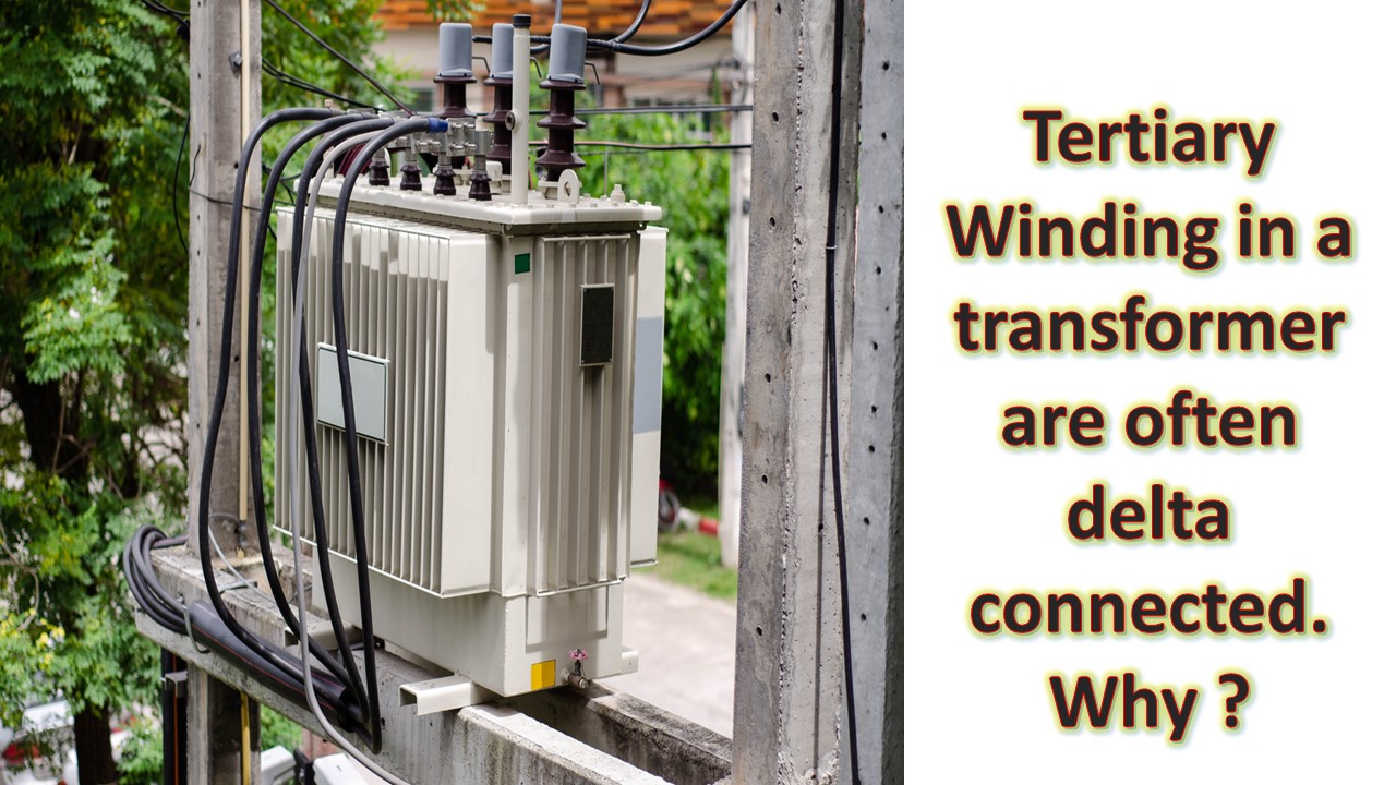
Transformers may be built with third winding, called the tertiary , in addition to the normal primary and secondary and such transformer are called the triple wound (or 3 winding ) transformers.
The tertiary winding may serve any of following Purposes.
- To supply the substation auxiliaries equipment's at a voltage which is different from those of the primary winding and secondary windings.
- To supply phase compensating devices, such as condensers operated at a voltage which different from both primary and secondary voltages.
- To connected to each other three supply systems which is operating at different voltages.
- To load large split winding generators.
- Used to measure high voltage of an High Voltage testing Transformer.
- In star/star connected transformers, to allow sufficient fault current to flow for operation of protective equipment, to suppress harmonic voltages and to limit voltage unbalance when the main load is symmetrical.
The tertiary winding is called the auxiliary winding when it is employed for supplying an additional small load at a different voltage. on the other hand it is called the stabilizing winding when it is employed to limit short circuit current.
Tertiary Winding in a transformer are often delta connected. Why ?
Ans: The tertiary windings are normally delta connected so that when fault and short circuit occur on the primary or secondary sides(particularly between lines and earth), the considerable unbalance produced in phase voltages may be reduced by the circulating currents flowing in the closed delta system.
The reactance of the windings should be large enough to limit the circulating currents in order that there is no over heating of the winding.
Also Read
What is induction Voltage regulator ?
Ans: The fundamental principal of transformer action requires that primary and secondary windings be coupled electromagnetically.
When the flux created by primary passes through the secondary winding, maximum emf is induced in the latter.
How ever if the secondary is rotated and brought into such a position that the flux passes across (not through) it, no emf will induced in it.
The idea of rotating the primary with respect to secondary is applied in the induction Voltage regulator.
The Induction Voltage regulator is essentially a stepdown transformer, but is so constructed that the secondary voltage may be varied from zero to a certain maximum value, dependent upon the ratio of turns in the two winding, merely by altering the position of the primary coil axis with respect to the secondary coil axis.
The primary winding is connected across the circuit to be regulated and the secondary is connected series with the circuit.
An induction voltage regulator may be of single phase or three phase type and comprises of stator and a rotor.

